-
PRODUCTS & SERVICESOptimized cooling solutions for modern data centersProducts & ServicesOptimized cooling solutions for modern data centers
-
CAPABILITIESAdvancing liquid cooling technologiesCapabilitiesAdvancing liquid cooling technologies
-
TechnologiesLiquid Cooling InnovationTechnologiesLiquid Cooling Innovation
-
RESOURCESLatest News & InformationResourcesLatest News & Information
-
ABOUTOur history, leadership and ownershipAboutOur history, leadership and ownership
-
CONTACTFacility locations and global operational footprint





What Is a Wired Push Button and How Does It Work?
A Wired Push Button is a simple control device that sends an electrical signal through a physical cable. Pressing its actuator changes the position of internal contacts. That change can start a motor, activate a doorbell, trigger an alarm, or control industrial equipment. The principle is simple. Small switch, clear action.
Inside the housing, the button usually connects a common terminal to a normally open or normally closed contact. A normally open circuit stays disconnected until someone presses the button. A normally closed circuit remains connected until pressure interrupts it. The connected control system detects this change and responds through a relay, controller, or input module. Wire size, voltage rating, contact capacity, and insulation quality all affect safe performance. A qualified installer should verify these details before connection.
Its value comes from reliability and direct feedback. You can feel the button move and often hear a distinct click. This makes troubleshooting easier, especially beside a machine or access panel. However, a wired design is not automatically safer or better. Poor terminals, loose conductors, moisture, and repeated mechanical stress can cause intermittent operation. That weakness is easy to overlook. This guide explains how a Wired Push Button works, how its terminals are arranged, and where installation choices matter. It also considers practical limitations, because real systems rarely behave as perfectly as diagrams suggest. Manufacturer specifications and appropriate electrical practices should guide every final decision.
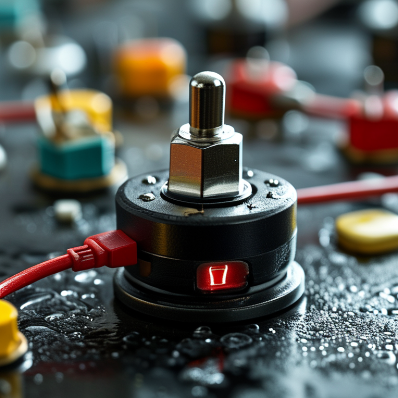
Table of Contents [Hide]
What Is a Wired Push Button?
A wired push button is a manually operated electrical switch connected through physical wires. Pressing its actuator changes the circuit between its terminals. Unlike wireless controls, it does not depend on batteries, radio signals, or software pairing. This simple design makes it useful in control panels, door systems, alarms, and small machines.
Most wired push buttons use normally open or normally closed contacts. A normally open button keeps the circuit broken until someone presses it. A normally closed button allows current to flow until pressure interrupts it.
Some buttons are momentary, so the contact changes only while pressed. Others stay in position after activation. The housing may include screw terminals, spring terminals, or solder tabs.
During a practical inspection, a multimeter can confirm the contact behavior before installation. Set it to continuity mode, touch the probes to the terminals, and press the button slowly. The reading should change clearly. It should not flicker repeatedly. That problem may indicate contact bounce, dirt, or a worn mechanism. The label alone is not enough. Check the voltage, current rating, wire size, and enclosure protection. A button rated for a low-voltage signal may fail in a power circuit. I also prefer testing the complete circuit, because a correct switch can still connect to the wrong terminals. Simple does not always mean foolproof.