-
PRODUCTS & SERVICESOptimized cooling solutions for modern data centersProducts & ServicesOptimized cooling solutions for modern data centers
-
CAPABILITIESAdvancing liquid cooling technologiesCapabilitiesAdvancing liquid cooling technologies
-
TechnologiesLiquid Cooling InnovationTechnologiesLiquid Cooling Innovation
-
RESOURCESLatest News & InformationResourcesLatest News & Information
-
ABOUTOur history, leadership and ownershipAboutOur history, leadership and ownership
-
CONTACTFacility locations and global operational footprint





Why Is an Air Humidity Sensor Important?
Why Is an Air Humidity Sensor Important?
Air humidity affects comfort, materials, machines, and health. Yet humidity is often treated as a minor reading on a wall display. That assumption can become expensive. A small change in moisture may warp wooden flooring, damage stored electronics, or encourage mold inside a poorly ventilated room.
Dr. Mark G. Lawrence, a recognized humidity researcher, explains, “Relative humidity compares the water vapor in air with the maximum amount that air can hold at its temperature.” This principle shows why an Air Humidity Sensor must measure humidity alongside temperature. Warm air and cool air can hold different amounts of moisture. The same reading may therefore describe different real conditions.
In practice, sensor placement matters. A device near a window may detect cold glass instead of room conditions. A sensor beside an air outlet may report unusually dry air. Dust, condensation, aging, and weak calibration can also distort results. The display may look precise. The measurement may still be wrong.
An Air Humidity Sensor provides useful evidence for controlling indoor environments, protecting products, and improving energy decisions. It supports ventilation systems, greenhouses, warehouses, laboratories, and museums. Good monitoring does not mean trusting every number. It means checking the sensor, its location, and its surrounding temperature.
This point deserves reflection. A sensor cannot fix excessive moisture by itself. It only reveals a condition that people must understand and manage. Reliable data begins with suitable equipment and careful interpretation.
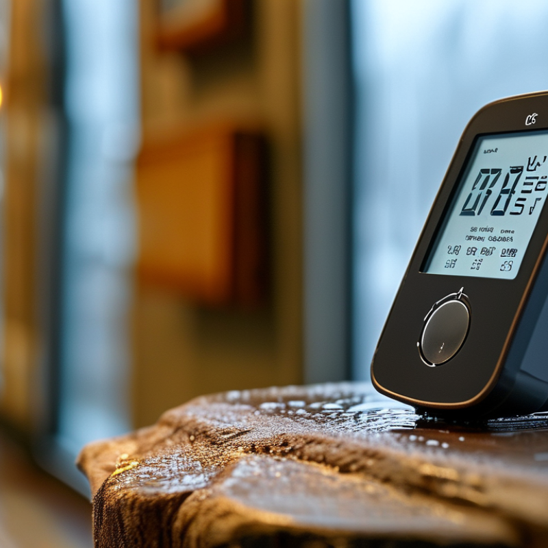
Table of Contents [Hide]
What Is an Air Humidity Sensor?
Why Is an Air Humidity Sensor Important?
An air humidity sensor measures the amount of water vapor in indoor air. Most models report relative humidity, or RH, as a percentage. A capacitive sensor changes its electrical response as moisture levels shift. Its circuit then converts that change into a readable RH value.
This device does more than display a number. It helps identify conditions that may support mold, dry skin, static electricity, or material damage. The U.S. Environmental Protection Agency recommends keeping indoor relative humidity between 30% and 50%. ASHRAE Standard 55 also uses humidity as an important factor in thermal comfort. A sensor can reveal a damp corner before condensation appears on a window. It can also expose overly dry air near a heater. Small errors remain possible. Dust, poor placement, and calibration can distort readings.
Tips: Place the sensor away from windows, vents, kitchens, and direct sunlight. Compare its reading with a second calibrated instrument when accuracy matters. Check trends, not only single readings. A value of 45% may look safe, but a hidden wall can still remain wet. The sensor reports air conditions, not every moisture problem. EPA indoor air quality guidance supports regular ventilation and moisture control. Use the reading as evidence, then inspect the room carefully.