-
PRODUCTS & SERVICESOptimized cooling solutions for modern data centersProducts & ServicesOptimized cooling solutions for modern data centers
-
CAPABILITIESAdvancing liquid cooling technologiesCapabilitiesAdvancing liquid cooling technologies
-
TechnologiesLiquid Cooling InnovationTechnologiesLiquid Cooling Innovation
-
RESOURCESLatest News & InformationResourcesLatest News & Information
-
ABOUTOur history, leadership and ownershipAboutOur history, leadership and ownership
-
CONTACTFacility locations and global operational footprint







China Top USB C Bulkhead Connector Manufacturers
China’s leading USB-C bulkhead connector manufacturers serve a market shaped by faster charging, compact equipment, and demanding installation environments. A bulkhead connector passes through a panel, allowing a secure external connection on industrial controllers, vehicles, test instruments, and sealed enclosures. Small details matter: thread fit, panel thickness, sealing method, and cable strain relief can determine whether a connector performs reliably after repeated use.
The USB Implementers Forum’s USB Power Delivery Revision 3.1 specification supports power levels up to 240 watts with Extended Power Range equipment. That figure makes thermal design, contact quality, and clearly stated product ratings especially important. USB-IF president and COO Jeff Ravencraft has described USB-C as “the one cable that can do it all.” The phrase captures the format’s ambition, though a bulkhead connector still needs careful matching to its cable, device, and operating conditions.
This guide examines China-based suppliers through practical criteria: published specifications, material choices, testing information, customization capability, and communication quality. A polished product page is not proof of field reliability. Buyers should request drawings, compatibility details, and relevant test records before comparing quotations. Look closely. A connector may appear identical in a photograph yet differ in sealing, pin configuration, or mounting tolerance. These differences are easy to overlook, and supplier claims deserve verification. The sections ahead introduce manufacturers and help technical buyers assess each Usb C Bulkhead Connector option with evidence rather than assumptions.
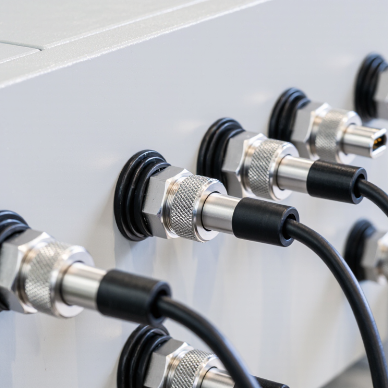
Table of Contents [Hide]
What USB-C Bulkhead Connectors Are and How They Work
China Top USB C Bulkhead Connector Manufacturers
What USB-C Bulkhead Connectors Are and How They Work
A USB-C bulkhead connector mounts through an enclosure wall, creating an accessible port while keeping internal wiring protected. The outer receptacle accepts a USB-C plug; contacts behind the panel connect to a cable or circuit board. A threaded shell, retaining nut, or gasket may secure the fitting.
Check the panel thickness and cutout dimensions before installation. Even a small mismatch can leave the connector loose or compromise the seal.
The connector carries power and data through matched contacts, but a bulkhead fitting does not set the performance by itself. USB-IF specifications define the Type-C interface, while the cable, host, and connected device determine which functions work. USB-IF’s USB Power Delivery 3.1 documentation allows up to 240 watts with Extended Power Range. Its USB4 Version 2.0 announcement describes data rates up to 80 Gbps.
Not automatically. Those are interface capabilities, not guarantees for every panel connector. Contact quality, cable length, shielding, and assembly all matter.
A practical check is to confirm the rated current and data speed, then test the complete assembly under load.
One detail is easy to overlook: a connector may fit neatly yet still limit signal performance. That trade-off deserves attention.