-
PRODUCTS & SERVICESOptimized cooling solutions for modern data centersProducts & ServicesOptimized cooling solutions for modern data centers
-
CAPABILITIESAdvancing liquid cooling technologiesCapabilitiesAdvancing liquid cooling technologies
-
TechnologiesLiquid Cooling InnovationTechnologiesLiquid Cooling Innovation
-
RESOURCESLatest News & InformationResourcesLatest News & Information
-
ABOUTOur history, leadership and ownershipAboutOur history, leadership and ownership
-
CONTACTFacility locations and global operational footprint




Top 10 Versal Board Manufacturers for Global Buyers
Selecting a Versal Board supplier is not just a price comparison. Buyers must assess design support, manufacturing controls, traceability, and delivery capacity. These details matter when a board must fit a defined power, thermal, and interface envelope. A polished product page is useful, but it is not proof of production capability.
The market context is expanding. The World Semiconductor Trade Statistics (WSTS) Fall 2024 forecast estimated global semiconductor sales at $627.6 billion in 2024 and $697.2 billion in 2025. This forecast describes the wider chip market, not Versal Board demand specifically. Still, it helps explain why buyers face more options—and why careful supplier checks remain essential. AMD’s Versal product documentation also gives buyers a technical baseline for evaluating device families, interfaces, and design requirements. Start there. Then compare each manufacturer’s board-level evidence.
This guide examines ten manufacturers serving global buyers, with attention to engineering depth, customization, quality processes, and communication across regions. Ask for concrete proof: test procedures, revision controls, sample lead times, and support for integration issues. A supplier may publish impressive specifications yet provide limited documentation. That gap can be easy to miss. No ranking can replace direct technical review, and company capabilities may change over time. The comparisons that follow are a starting point—not a substitute for checking the exact board, project requirements, and current manufacturing terms.
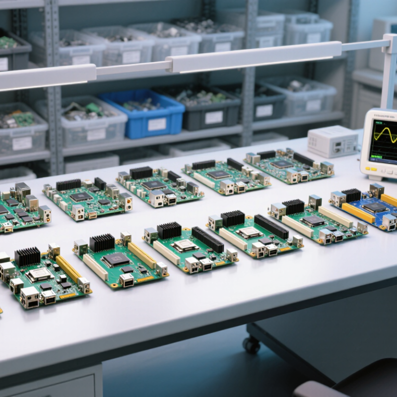
Table of Contents [Hide]
Define Versal ACAP Boards and Their 7 nm Adaptive-Compute Foundation
Versal ACAP boards combine programmable logic, processing systems, and adaptable compute resources on a 7 nm foundation. The term ACAP describes an adaptive compute platform: hardware can be configured for specific workloads rather than relying only on fixed-function processors. On a board, this flexibility supports tasks such as signal processing, data movement, and machine-learning inference. The exact mix of resources varies by device and board design.
Details matter.
The 7 nm process enables dense integration, but it does not guarantee lower system power or higher performance in every application. Cooling, memory bandwidth, software tools, and workload design all shape real results. A compact board still needs careful thermal planning; airflow around heat sinks can make a measurable difference.
The Semiconductor Industry Association reported global semiconductor sales of $627.6 billion in 2024, underscoring the scale of demand for advanced computing components. That figure describes the wider chip market, not ACAP boards specifically.
Buyers should compare published specifications with measured board-level results. One caveat: headline compute figures can obscure bottlenecks in memory access and data transfer. That deserves scrutiny.