-
PRODUCTS & SERVICESOptimized cooling solutions for modern data centersProducts & ServicesOptimized cooling solutions for modern data centers
-
CAPABILITIESAdvancing liquid cooling technologiesCapabilitiesAdvancing liquid cooling technologies
-
TechnologiesLiquid Cooling InnovationTechnologiesLiquid Cooling Innovation
-
RESOURCESLatest News & InformationResourcesLatest News & Information
-
ABOUTOur history, leadership and ownershipAboutOur history, leadership and ownership
-
CONTACTFacility locations and global operational footprint






10 Tips for Choosing Moulded Case Circuit Breakers
Choosing Moulded Case Circuit Breakers is not just a matter of matching an ampere rating. The right device must suit the circuit, the expected fault current, and the conditions inside the enclosure. A breaker selected without checking these details may trip too often—or fail to provide the intended protection. Details matter.
This guide presents ten practical tips for comparing breakers before purchase or installation. It explains how to review rated current, voltage, interrupting capacity, trip characteristics, pole configuration, and coordination with upstream and downstream devices. It also considers ambient temperature, available panel space, terminal compatibility, and access for inspection. Each factor can affect performance in a real installation. A neat specification sheet can still hide a poor fit.
Reliable selection starts with the equipment manufacturer’s documentation and the system’s design requirements. Where calculations, coordination studies, or local installation rules apply, qualified electrical professionals should verify the choice. Product labels and online listings alone may not show how a breaker behaves under the site’s actual conditions. That is worth remembering. The ten tips that follow are intended to make comparisons clearer, highlight questions to ask suppliers, and reduce avoidable mismatches. They are not a substitute for engineering review. Even experienced buyers can overlook one small detail, such as a terminal limitation or a temperature-related rating adjustment. A careful check is usually faster than correcting the wrong selection later.
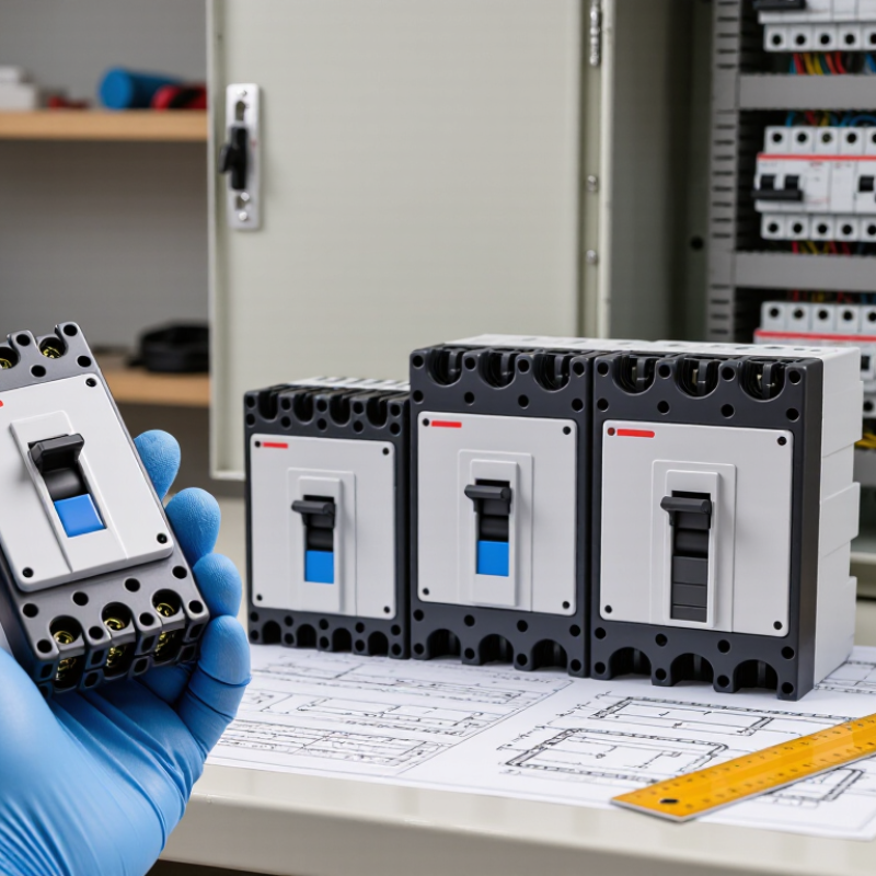
Table of Contents [Hide]
Understand the Role and Applications of Moulded Case Circuit Breakers
Moulded case circuit breakers (MCCBs) protect electrical circuits from excessive current caused by overloads or short circuits. They interrupt current before overheating damages cables, equipment, or connected loads. Their role is practical: limit fault damage and help keep an installation operating safely. They are commonly installed in distribution boards and control panels.
MCCBs suit circuits carrying more current than many miniature breakers can handle. You may find them protecting building feeders, workshop machinery, pumps, and motor circuits. Some models offer adjustable trip settings, which can help match protection to the cable and load. That matters. A breaker set too high may not protect its cable adequately; set too low, it may trip during normal operation.
Choosing one involves more than matching the current rating. Check the system voltage, available fault current, pole count, and the manufacturer’s trip characteristics. Confirm that the breaking capacity is suitable for the installation’s likely fault level. Coordination with upstream and downstream protection also matters, though it is sometimes overlooked. Not always. Real operating conditions can differ from a neat design sheet, so verify settings and installation details with a qualified electrical professional.
| No. | Selection Tip | What to Check | Practical Guidance |
|---|---|---|---|
| 1 | Define the circuit’s role | Identify whether the breaker protects a feeder, motor circuit, transformer, generator, or other load. | Consider normal operating current, inrush or starting current, and the characteristics of the connected equipment before choosing trip settings. |
| 2 | Match the current rating to the circuit | Check the load current, conductor ampacity, installation conditions, and applicable electrical codes. | Select a rating and settings that provide suitable overload protection without exceeding the permitted current for the conductors or equipment. |
| 3 | Verify voltage and frequency suitability | Confirm the breaker’s rated operational voltage, system type (AC or DC), and frequency are suitable for the application. | Use the ratings specified for the actual system. Do not assume an AC rating also applies to DC circuits. |
| 4 | Choose the required number of poles | Determine whether the circuit requires one-, two-, three-, or four-pole switching and protection. | Base the choice on the system configuration and local rules, including how neutral conductors must be treated. |
| 5 | Check short-circuit breaking capacity | Compare the prospective short-circuit current at the installation point with the breaker’s rated ultimate breaking capacity (Icu). | The breaker’s applicable breaking capacity must be adequate for the available fault current at its rated voltage. |
| 6 | Review service breaking capacity | Check the rated service short-circuit breaking capacity (Ics), where specified, as well as Icu. | Ics indicates the breaker’s ability to remain serviceable after specified short-circuit tests. Select a suitable value for the required continuity of service. |
| 7 | Select the appropriate trip unit | Compare thermal-magnetic and electronic trip options, available protection functions, and adjustment ranges. | Use settings suited to the load and protection study. Electronic trip units may offer adjustable protection and additional functions, depending on the model. |
| 8 | Assess coordination with other devices | Review time-current curves and coordination information for upstream and downstream protective devices. | Where continuity is important, verify selectivity or discrimination using the applicable manufacturer data and system fault levels. |
| 9 | Account for installation conditions | Check ambient temperature, enclosure conditions, altitude, mounting orientation, terminal limits, and available space. | Apply any specified derating or installation limits. Confirm that the enclosure and connections support safe heat dissipation and the required clearances. |
| 10 | Confirm standards and accessories | Check compliance with the standards required in the installation region, such as IEC 60947-2 or UL 489, as applicable. | Verify that accessories—such as auxiliary contacts, shunt trips, or undervoltage releases—are compatible and meet the control and monitoring requirements. |