-
PRODUCTS & SERVICESOptimized cooling solutions for modern data centersProducts & ServicesOptimized cooling solutions for modern data centers
-
CAPABILITIESAdvancing liquid cooling technologiesCapabilitiesAdvancing liquid cooling technologies
-
TechnologiesLiquid Cooling InnovationTechnologiesLiquid Cooling Innovation
-
RESOURCESLatest News & InformationResourcesLatest News & Information
-
ABOUTOur history, leadership and ownershipAboutOur history, leadership and ownership
-
CONTACTFacility locations and global operational footprint







How to Test a PCB for Electrical Faults?
A PCB can appear clean while a cracked solder joint, reversed component, or damaged trace interrupts its operation. These faults may cause a device to fail intermittently, draw excessive current, or remain completely unresponsive. Careful electrical testing helps narrow the cause before parts are replaced. It also reduces the risk of overlooking a simple assembly problem.
This guide explains Electrical Testing Pcb methods, from visual inspection and continuity checks to resistance and voltage measurements. A digital multimeter, a clear schematic, and the board’s expected values provide a practical starting point. With power disconnected, inspect connector pins, solder joints, and areas around heat-producing components. Then check for unintended shorts between power and ground. Small details matter.
When the board needs power, use a current-limited supply and follow its rated input range. Measure at labeled test points, comparing readings with the design documentation rather than guessing. Record each result. Unexpected readings deserve a second check; probes can slip, and a poor ground reference can mislead even experienced technicians. No test is perfect. Some faults appear only under load or after warming up, so one normal reading does not prove the board is healthy. A disciplined process makes troubleshooting safer and more repeatable, while leaving room to reconsider an early assumption.
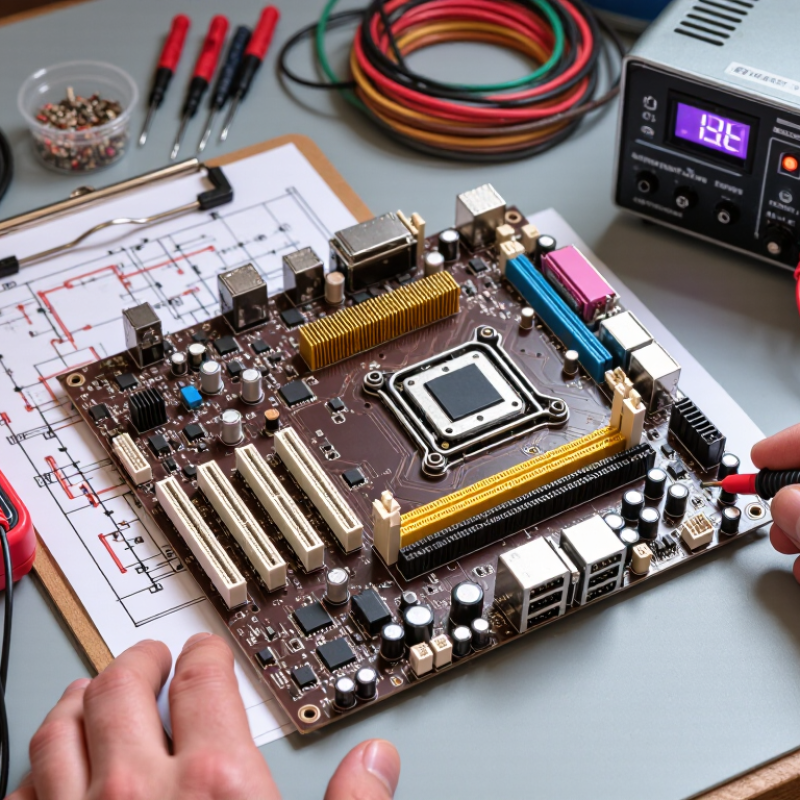
Table of Contents [Hide]
Identify Symptoms and Prepare the PCB for Testing
Electrical faults often show through small, repeatable clues. A board may fail to start, reset under load, or lose one function while others work. Note when the problem appears: during startup, after warming, or when a connector moves. Small clues matter. Look for darkened areas, cracked solder joints, lifted pads, corrosion, or components that feel unusually hot. A burnt smell is useful evidence, but do not power the board again just to confirm it.
Prepare the PCB before taking measurements. Disconnect its power source and attached cables, then wait for stored charge to dissipate. Some capacitors can retain voltage, so verify with a meter rather than relying on appearance. Work on a clean, dry surface, and use basic electrostatic precautions. Photograph the board and mark connectors before removing anything; small wiring details are easy to forget.
Start with a careful visual inspection under bright light. Check for loose metal fragments, solder bridges, and damaged insulation. With power off, a multimeter’s continuity or resistance mode can help locate unexpected shorts between supply and ground. Compare readings across similar sections when possible. A low reading is not automatically a fault; circuit components can affect it. It is tempting to rush toward a single bad part, but the symptom may come from a connector, solder joint, or damaged trace instead.
How to Test a PCB for Electrical Faults? - Identify Symptoms and Prepare the PCB for Testing
| Stage or symptom | Possible fault | Preparation or test | What to check | Interpretation and next step |
|---|---|---|---|---|
| Before testing | Unintended damage during inspection or measurement | Disconnect power and external cables; isolate batteries; discharge capacitors safely; use ESD precautions. Review the schematic or board documentation. | Confirm the board is unpowered before resistance or continuity tests. Identify ground, input, and supply test points. | Never measure resistance on an energized circuit. If stored voltage remains, wait or discharge it using an appropriate method before proceeding. |
| No power or intermittent operation | Cracked solder joint, damaged connector, broken trace, or faulty input protection component | Inspect both sides under good lighting or magnification. Check connectors, solder joints, fuses, and areas near mechanical stress or heat. | Look for lifted pads, cracked joints, corrosion, discoloration, or damaged components. With power off, check continuity across suspected traces or connections. | A discontinuity where the schematic shows a direct connection suggests an open path. Repair and retest; visual appearance alone does not confirm electrical integrity. |
| Supply does not start or a fuse opens | Short circuit on a power rail, reversed component, or failed power-input component | With power removed, use a multimeter in resistance or continuity mode between the rail and ground. Check the meter-lead resistance first. | A persistent near-zero resistance may indicate a short, but capacitors can cause a temporarily low reading and semiconductor paths can affect continuity mode. | Compare readings with the circuit design and allow capacitors to settle. Do not treat a continuity beep alone as proof of a fault; isolate sections if the low resistance persists. |
| One rail is missing or outside specification | Failed regulator, open feed, overload, or short on a downstream rail | After unpowered checks, energize only when safe. Use a current-limited bench supply set to the board's documented input voltage and an appropriate current limit. | Measure the input and each rail at documented test points. Compare readings with schematic or component specifications; monitor input current and temperature. | A low or absent rail can result from either the regulator path or a downstream load. Power down before disconnecting loads or making resistance measurements. |
| Unexpected resets, noise, or unstable readings | Poor grounding, loose connection, inadequate decoupling, or unstable supply | Check connector seating and ground connections. If available, use an oscilloscope with an appropriate probe and safe grounding practice. | Observe the supply rail during the fault and check for dips, excessive ripple, or intermittent dropouts. Compare against the circuit's specified limits. | A multimeter may not capture brief transients. Confirm the measurement setup and probe connection before concluding that the PCB is faulty. |
| Component heats rapidly or board draws excessive current | Shorted component, incorrect polarity, wrong assembly, or overloaded output | Stop the test if current rises unexpectedly, a component becomes hot, or there is smoke or odor. Disconnect power and inspect the affected area. | Check component orientation and markings against the design, then test suspect parts using suitable methods and with the circuit unpowered. | Do not touch a hot board or repeatedly reapply power. Correct the suspected cause and verify current and rail voltages under controlled conditions. |
Note: Voltage limits and acceptable resistance values depend on the specific PCB design. Use its schematic, test documentation, and component datasheets as the reference.