-
PRODUCTS & SERVICESOptimized cooling solutions for modern data centersProducts & ServicesOptimized cooling solutions for modern data centers
-
CAPABILITIESAdvancing liquid cooling technologiesCapabilitiesAdvancing liquid cooling technologies
-
TechnologiesLiquid Cooling InnovationTechnologiesLiquid Cooling Innovation
-
RESOURCESLatest News & InformationResourcesLatest News & Information
-
ABOUTOur history, leadership and ownershipAboutOur history, leadership and ownership
-
CONTACTFacility locations and global operational footprint




10 Roller Conveyor Buying Tips for Global Buyers?
Buying a Roller Conveyor is rarely a simple matter of choosing length, speed, and price. In a real warehouse, cartons arrive unevenly, operators change layouts, and dust settles on bearings. A conveyor that performs well in a showroom may struggle beside a loading dock. Experience matters here, but experience alone can mislead.
The International Federation of Robotics reported 541,302 industrial robot installations worldwide in its World Robotics 2024 report. This figure reflects broader investment in automated material handling and connected production. MHI’s 2024 Annual Industry Report also identifies technology adoption, labor pressure, and supply-chain resilience as major industry concerns. These trends make conveyor selection more strategic. However, the reports do not replace site measurements or engineering checks.
Small details decide performance.
This guide presents ten practical Roller Conveyor buying tips for global buyers. It examines roller diameter, load capacity, frame materials, drive systems, accumulation methods, controls, safety features, and maintenance access. It also considers voltage compatibility, regional standards, spare-parts availability, and supplier support after installation. CEMA conveyor guidance and manufacturer documentation should support the final specification, especially for heavy loads or integrated systems.
A lower quotation may appear efficient. It may also exclude sensors, guarding, commissioning, or replacement rollers. That is an easy mistake. Buyers should compare total ownership cost, not only the purchase invoice. No guide can remove every uncertainty, and some recommendations may need revision after testing actual cartons, pallets, and operating temperatures. Reliable decisions come from verified data, clear drawings, and honest discussions with qualified suppliers.
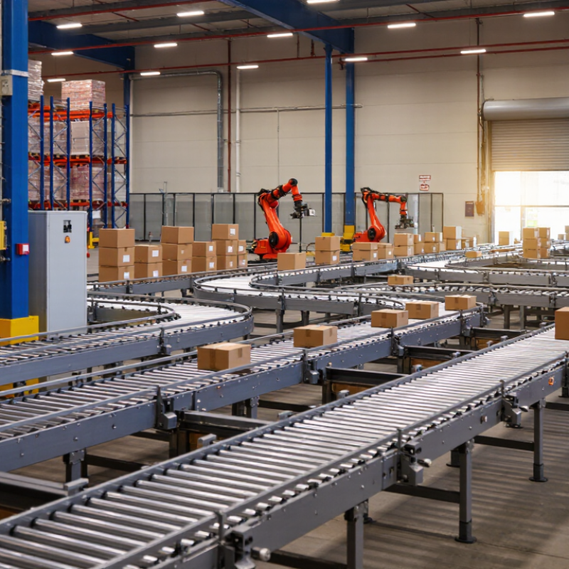
Table of Contents [Hide]
Define Requirements: Throughput, Load Profile, and 50–100 mm Roller Diameters
Before selecting a roller conveyor, define the real throughput, not the hoped-for figure. Record cartons per minute during normal and peak shifts. Include gaps between loads. A short test run helps.
Measure the load profile carefully. Note weight, length, width, base stiffness, and center of gravity. A rigid box may travel smoothly, while a flexible sack can sag between rollers. Heavy or uneven loads need closer roller spacing. The frame must also resist twisting during starts and stops.
Roller diameters from 50 to 100 mm suit many warehouse and production applications. Smaller rollers can reduce cost and handle compact packages effectively. Larger rollers usually offer better support for heavier loads and rougher operating conditions. Match the diameter with axle strength, bearing capacity, speed, and contact area. Do not judge by diameter alone.
A practical rule is to keep at least three rollers under the load, although irregular products may need more. Test the smallest package, not only the largest carton. It may wobble. It may stop.
Specify whether the conveyor moves continuously or indexes between stations. This changes motor sizing and control requirements. Ask suppliers for load charts, noise data, maintenance intervals, and actual operating limits. Confirm materials, guarding, emergency controls, and local installation requirements before purchase.
A neat calculation can still mislead. Dust, temperature changes, poor pallet bases, and rushed loading often reduce performance. Leave realistic capacity margin instead of designing for perfect conditions.