-
PRODUCTS & SERVICESOptimized cooling solutions for modern data centersProducts & ServicesOptimized cooling solutions for modern data centers
-
CAPABILITIESAdvancing liquid cooling technologiesCapabilitiesAdvancing liquid cooling technologies
-
TechnologiesLiquid Cooling InnovationTechnologiesLiquid Cooling Innovation
-
RESOURCESLatest News & InformationResourcesLatest News & Information
-
ABOUTOur history, leadership and ownershipAboutOur history, leadership and ownership
-
CONTACTFacility locations and global operational footprint






What Is an Impulse Voltage Generator and How Does It Work?
An Impulse Voltage Generator produces brief, controlled high-voltage pulses for testing electrical insulation. Engineers use these pulses to imitate lightning strikes and switching surges. The equipment helps assess transformers, cables, bushings, insulators, and other high-voltage components. Its purpose is practical: reveal weaknesses before a failure occurs in service.
The operating principle is straightforward, although the hardware is not. Several capacitors charge in parallel through resistors and charging circuits. Spark gaps then trigger almost simultaneously. The capacitors discharge in series, creating a much higher voltage at the test terminal. Wavefront and wave-tail resistors shape the pulse. Measuring systems record the result through a voltage divider and oscilloscope. A typical lightning impulse may rise within microseconds, then decay more slowly.
Small timing errors matter.
Experienced test engineers also control grounding, room clearance, humidity, and measurement bandwidth. These details can influence the recorded waveform. IEC 60060 guidance supports repeatable high-voltage testing, but standards do not replace careful judgment. A generator may produce an impressive peak voltage while still delivering an unsuitable waveform. That distinction is easy to miss. It is also where inexperienced testing can become misleading.
This article explains the main parts of an Impulse Voltage Generator and follows the energy path from charging to discharge. It also considers practical limitations, safety interlocks, waveform measurement, and common testing mistakes. The explanation remains focused on engineering use. Some designs vary considerably, so simplified diagrams should not be treated as complete operating instructions. Real systems require qualified personnel, calibrated instruments, and documented procedures.
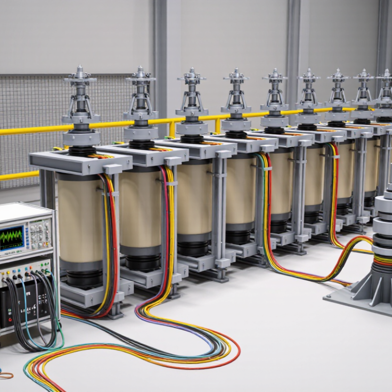
Table of Contents [Hide]
What Is an Impulse Voltage Generator?
What Is an Impulse Voltage Generator and How Does It Work?
An impulse voltage generator is a laboratory system that produces a short, high-voltage surge. Engineers use it to test insulation in transformers, cables, switchgear, and other power equipment. The surge imitates lightning or switching events that can stress electrical insulation during service. It is not a continuous power source. It delivers energy briefly, then stops.
The system usually charges several capacitors in parallel. Spark gaps then connect them in series, creating a much higher voltage. Resistors and capacitors shape the rising and falling edges of the pulse. According to IEC 60060-1, the standard lightning impulse waveform is 1.2/50 microseconds. Its front rises quickly, while the tail decays more slowly. IEEE Std 4-2013 defines measurement methods for these high-voltage tests. A voltage divider records the pulse, and an oscilloscope displays its actual shape. Small errors matter.
In practical testing, engineers compare the measured waveform with tolerance limits before accepting results. The test object may show puncture, surface flashover, or no visible damage. CIGRE technical guidance emphasizes controlled grounding, shielding, and measurement quality for reliable impulse testing. The generator’s design looks simple, but stray inductance can distort the pulse. That detail is easy to underestimate. Experienced technicians therefore inspect connections, calibration records, and room conditions before energizing the circuit. Perfect waveforms are rare, and that should encourage careful review rather than careless confidence.