-
PRODUCTS & SERVICESOptimized cooling solutions for modern data centersProducts & ServicesOptimized cooling solutions for modern data centers
-
CAPABILITIESAdvancing liquid cooling technologiesCapabilitiesAdvancing liquid cooling technologies
-
TechnologiesLiquid Cooling InnovationTechnologiesLiquid Cooling Innovation
-
RESOURCESLatest News & InformationResourcesLatest News & Information
-
ABOUTOur history, leadership and ownershipAboutOur history, leadership and ownership
-
CONTACTFacility locations and global operational footprint




How to Find China Top Air Conditioner Contactors?
Finding a reliable China top Air Conditioner Contactor supplier requires more than comparing online prices. The component controls compressor and fan motor power. A poor selection can create welded contacts, overheating, or repeated service calls. It may also damage the buyer’s reputation.
HVAC technical educator Jim Cika offers a practical reminder: “A contactor is only as good as the system around it.” This principle matters when evaluating Chinese manufacturers. Check the coil voltage, pole configuration, rated operational current, electrical life, and compatibility with the intended refrigerant system. Ask for clear product drawings and recent test reports. Do not rely on attractive photographs alone.
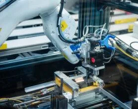
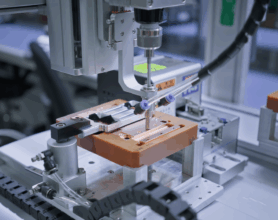
Visit the factory, if possible. Observe incoming copper inspection, coil winding, contact riveting, and final electrical testing. A serious supplier should explain its quality controls without hesitation. Request samples from the same production line used for mass orders. Test them under realistic loads, not only in an office environment.
Look for certifications suited to your target market, such as UL, IEC, or CCC documentation. Verify certificate numbers independently. Confirm whether the company is a manufacturer or only a trading intermediary. That distinction can affect traceability, customization, and technical support.
Price still matters. It should not lead the decision. A cheaper Air Conditioner Contactor may hide thinner silver alloy contacts or unstable coil insulation. I have seen buyers focus on unit cost and overlook warranty response time. That mistake is easy to repeat.
The best supplier combines stable production, transparent documents, responsive engineers, and consistent samples. Even then, no supplier is perfect. Recheck every critical detail before signing a long-term agreement.
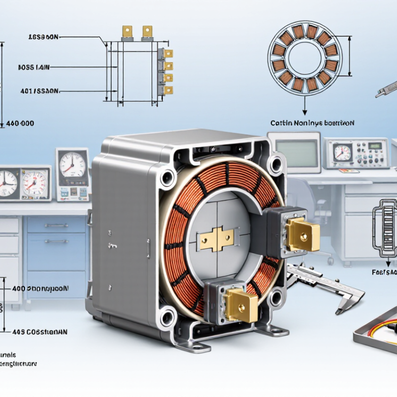
Table of Contents [Hide]
Understand the Role of Air Conditioner Contactors
How to Find China Top Air Conditioner Contactors?
An air conditioner contactor is an electrically controlled switch. It connects the compressor, condenser fan, or indoor blower to the power supply. Its coil receives a low-power control signal. The contacts then handle the motor’s higher current. This separation protects the control board and supports safer switching.
The International Energy Agency reported in The Future of Cooling that cooling uses about 10% of global electricity. It also projects cooling electricity demand could triple by 2050. These figures make contactor reliability more important, especially during repeated compressor starts. A suitable model should match voltage, current, frequency, pole count, coil type, and motor duty rating. Check IEC 60947-4-1 test compliance and request verified technical documents.
Do not trust appearance alone.
In practical sourcing, inspect contact spacing, terminal strength, coil noise, and temperature rise. Ask for samples and perform repeated start-stop tests under realistic loads. A contactor that works on a bench may fail inside a hot outdoor unit. I have seen specifications overlook inrush current, which is a costly mistake. Supplier audits, traceable test records, and consistent production samples provide stronger evidence than sales claims. Chinese manufacturers should also explain insulation ratings, mechanical life, and replacement availability clearly.