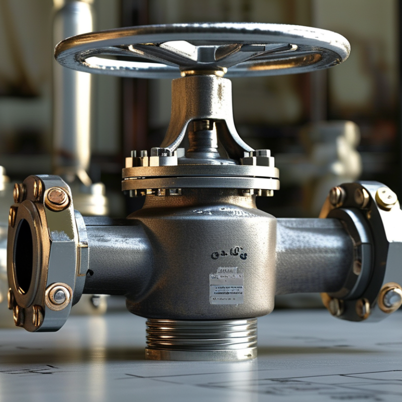
| Selection | Valve function | Use a bellows sealed gate valve for isolation service where the valve is normally fully open or fully closed. Do not use a gate valve as a routine throttling device because partially open operation can cause vibration, erosion, and damage to the seating surfaces. | Isolation service
Not recommended for continuous flow control |
| Selection | Nominal size | Select the nominal pipe size to match the connected piping unless a documented hydraulic study supports a different size. Check the bore, end connection, face-to-face dimension, and available operating space. | Common industrial sizes: DN15 to DN600
Typical equivalent range: NPS 1/2 to NPS 24
Confirm the exact size range with the valve design |
| Selection | Pressure class | Choose the pressure class from the design pressure and design temperature, not from operating pressure alone. The allowable pressure decreases as temperature increases and depends on the pressure-temperature rating of the body material. | Common classes: ASME Class 150, 300, 600, 900, and 1500
Typical PN options: PN16, PN25, PN40, PN63, PN100, and PN160
Use the applicable rating table |
| Selection | Temperature range | Verify the temperature limits of the body, bonnet, stem, bellows, packing, seat, gasket, and bolting as an assembled system. Consider start-up, shutdown, thermal cycling, and upset conditions. | Metal-bellows valves are commonly specified for cryogenic, ambient, and elevated-temperature services.
Use the manufacturer’s certified pressure-temperature envelope |
| Selection | Process medium | Check compatibility with the fluid, concentration, moisture content, contaminants, and phase changes. Select wetted materials and seat materials for corrosion, erosion, permeation, and thermal compatibility. | Typical body materials include carbon steel, stainless steel, and alloy steel.
Material selection must be based on the process chemistry and design conditions |
| Selection | Bellows material | Select the bellows alloy for corrosion resistance, fatigue life, temperature, pressure differential, and the required number of operating cycles. The bellows is a pressure boundary component and should not be treated as a replaceable packing element. | Common material families include austenitic stainless steels and nickel-based alloys.
Require a documented cycle-life calculation or test basis for critical service |
| Selection | Stem sealing arrangement | The bellows provides the primary dynamic stem seal. A secondary packing arrangement is commonly used above the bellows to provide backup sealing and containment if the bellows is damaged. | Primary seal: welded metal bellows
Secondary seal: packing or backup stem seal
Confirm the packing temperature and chemical limits |
| Selection | Emission control | For hazardous, toxic, volatile, or environmentally regulated media, specify a tested low-emission design and define the test method and acceptance level in the purchase specification. | ISO 15848-1 may be used for type testing of fugitive emissions.
ISO 15848-2 may be used for production acceptance testing.
Specify the required tightness class and temperature class |
| Selection | Body and bonnet design | Use a bolted, welded, or pressure-sealed bonnet according to pressure, temperature, maintenance, and plant requirements. The bonnet cavity should provide adequate space for the bellows and stem movement without overstressing the assembly. | Common construction: forged or cast body with an extended bonnet and welded bellows assembly
For cryogenic service, use a bonnet extension suitable for cold-box or low-temperature operation |
| Selection | End connections | Match the valve ends to the piping system and installation method. Flanged valves require compatible flange rating, facing, gasket, and bolting. Butt-weld ends require correct pipe wall thickness and welding procedure control. | Flange dimensions may be specified to ASME B16.5 or ASME B16.47 where applicable.
Butt-weld ends may be specified to ASME B16.25.
Verify end-to-end dimensions to ASME B16.10 where applicable |
| Selection | Flow direction and pressure relief | Review the manufacturer’s flow-direction requirement and determine whether the gate design is rising-stem, non-rising-stem, wedge, or parallel-slide. Assess trapped-pressure and thermal-expansion risks in the closed body cavity. | Install according to the marked flow direction when one is provided.
Provide a body-cavity relief arrangement when required by the valve design and process hazard review |
| Selection | Actuation and operating torque | For manual service, select a handwheel size that permits safe operation without impact tools. For automated service, size the actuator for breakaway, running, and closing torque, including seat load, differential pressure, temperature, and safety factor. | Actuator sizing must use certified valve torque data.
Do not estimate torque solely from nominal size or line pressure |
| Selection | Seat leakage requirement | Define the required shutoff class and test medium. Gate valves intended for isolation should be tested in accordance with the applicable valve standard and project specification. | API 598 is commonly used for inspection and pressure testing of industrial valves.
Acceptance limits depend on valve size, seat type, test medium, and applicable standard |
| Installation | Pipeline cleanliness | Remove weld slag, scale, rust, sand, gasket fragments, and other debris before installation. Foreign material can score the seats, obstruct the gate, or damage the bellows and stem assembly. | Flush or blow the line using a procedure suitable for the process and valve materials.
Keep the valve closed during line cleaning unless the procedure specifically requires otherwise |
| Installation | Valve orientation | Install the valve in the orientation recommended by the manufacturer. Keep the stem accessible, provide clearance for handwheel or actuator travel, and avoid placing loads on the bonnet or bellows assembly. | Provide sufficient clearance for full stem travel and maintenance removal.
Do not use the valve as a support for piping or cable trays |
| Installation | Piping alignment | Align the pipe ends before bolting or welding. Do not force the valve into position, use flange bolts to correct misalignment, or apply bending loads that can distort the body and seats. | Check angular, lateral, and rotational alignment before final connection.
Support adjacent pipework independently of the valve |
| Installation | Flange assembly | Use a new gasket of the correct material and rating. Tighten bolts in a gradual, alternating cross-pattern using a calibrated torque procedure appropriate for the bolt material and lubricant. | Follow the project flange-bolting procedure.
Do not reuse compressed gaskets unless specifically approved for the service |
| Installation | Butt-weld installation | Confirm weld-end dimensions and pipe wall thickness. Protect the valve from excessive heat, weld spatter, and distortion. Use a qualified welding procedure and prevent contamination of the internal cavity. | Use qualified welders and approved WPS/PQR documentation where required.
Control preheat, interpass temperature, purge, and post-weld treatment according to material and code requirements |
| Installation | Pressure testing | Test the installed valve and piping in accordance with the project specification and applicable code. Use a clean test medium compatible with the valve materials and process cleanliness requirements. | Typical tests include body shell testing, seat leakage testing, and bellows or stem-seal leakage verification where specified.
Record test pressure, duration, medium, temperature, and result |
| Installation | Initial operation | Operate the valve slowly through the full travel after testing and line flushing. Confirm smooth movement, correct position indication, tight shutoff, and absence of abnormal noise or vibration. | Open and close fully without impact loading.
Never use a wrench, cheater bar, or impact tool unless the valve manufacturer expressly permits it |
| Maintenance | Routine inspection | Inspect the valve body, bonnet joint, stem, packing area, bellows monitoring connection, flanges, welds, and nearby pipe supports. Look for leakage, corrosion, frost, abnormal temperature, vibration, and damage to the position indicator. | Inspection frequency should be risk-based and defined by the plant maintenance program.
Increase inspection frequency for hazardous or cycling service |
| Maintenance | Operating cycle control | Minimize unnecessary cycling. Excessive or rapid movement increases bellows fatigue and seat wear. Record operating cycles for critical valves and compare them with the design qualification basis. | Bellows life is application-specific and depends on stroke, pressure, temperature, vibration, and cycle frequency.
Use the documented design or test cycle rating |
| Maintenance | Stem and packing condition | Keep the stem clean and inspect the secondary packing for leakage or deterioration. Do not overtighten packing because excessive friction can increase operating torque and load the stem and bellows. | Adjust or replace packing only according to the valve maintenance procedure.
Any suspected primary bellows leak requires controlled isolation and specialist repair |
| Maintenance | Bellows leak monitoring | Where a bellows monitoring port or interspace is provided, inspect or test it according to the manufacturer’s procedure. A leak indication should be treated as a pressure-boundary warning, not as a normal packing adjustment issue. | Use the specified detection medium and test method.
Remove the valve from hazardous service before dismantling if bellows integrity is in doubt |
| Maintenance | Seat and gate condition | Do not force the handwheel when the gate is stuck. Investigate differential pressure, debris, thermal binding, stem damage, actuator problems, or body-cavity pressure before applying additional operating force. | Gate valves should reach the fully open or fully closed position without abnormal torque.
Repair or replace damaged seating components using qualified procedures |
| Maintenance | Periodic testing | Perform functional, shell, seat, and fugitive-emission tests when required by the plant integrity program, regulatory requirements, or service risk assessment. | Maintain test records including valve tag, size, class, test method, leakage result, cycle count, and corrective actions |
| Maintenance | Overhaul and replacement | During overhaul, inspect the bellows welds, stem, guide, gate, seats, bonnet gasket, packing, bolting, and corrosion allowance. Replace pressure-boundary components only with materials and procedures approved for the valve design. | Use qualified technicians, controlled assembly procedures, and post-repair pressure and leakage testing.
Do not weld or repair a bellows pressure boundary without an approved engineering procedure |
| Documentation | Procurement data sheet | Provide complete process, mechanical, materials, testing, emission, actuation, and documentation requirements before ordering. Incomplete data can result in an unsuitable pressure class, bellows alloy, seat material, or end connection. | Minimum data: fluid, phase, composition, flow direction, design pressure, design temperature, size, pressure class, end type, material standard, leakage class, emission requirement, actuator requirement, and applicable codes |