-
PRODUCTS & SERVICESOptimized cooling solutions for modern data centersProducts & ServicesOptimized cooling solutions for modern data centers
-
CAPABILITIESAdvancing liquid cooling technologiesCapabilitiesAdvancing liquid cooling technologies
-
TechnologiesLiquid Cooling InnovationTechnologiesLiquid Cooling Innovation
-
RESOURCESLatest News & InformationResourcesLatest News & Information
-
ABOUTOur history, leadership and ownershipAboutOur history, leadership and ownership
-
CONTACTFacility locations and global operational footprint




How to Choose an Electric Coolant Heater for Global Sourcing?
Choosing an Electric Coolant Heater for global sourcing is more than comparing wattage and unit prices. The correct choice must match the vehicle platform, coolant circuit, operating climate, and electrical architecture. A heater designed for a 400-volt system may fail completely on an 800-volt platform. Small details matter.
Dr. Stefan Götz, an automotive thermal-management specialist, offers a practical sourcing principle: “Measure the heat path before you measure the price.” This advice keeps purchasing teams focused on thermal output, pressure drop, response time, and durability. Buyers should request verified performance curves, insulation data, ingress protection ratings, electromagnetic compatibility records, and traceable material documentation. Supplier experience with cold-start testing is also valuable. Ask for evidence, not polished promises.
Global sourcing adds another layer of risk. Voltage tolerance, connector design, coolant compatibility, ambient temperature, packaging, and regional certification expectations must be reviewed together. A supplier may offer a competitive quotation but lack stable production capacity. That weakness often appears later, through inconsistent samples or delayed replacement parts. It is not always visible in a brochure.
Test the heater with the intended coolant and control strategy. Check thermal behavior at low temperatures. Review service access and warranty terms. Conduct a factory audit when volumes justify it. No checklist is perfect. I have seen technically strong products lose value through poor communication and weak documentation. This guide explains how to balance engineering evidence, supplier reliability, total cost, and long-term support when selecting an Electric Coolant Heater for international procurement.
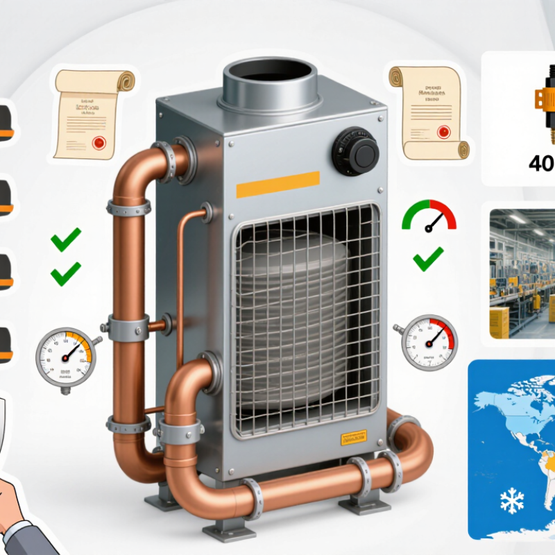
Table of Contents [Hide]
Define the Heating Requirements for Your Vehicle or Equipment
How to Choose an Electric Coolant Heater for Global Sourcing?
Define the heating requirements before comparing suppliers or prices. Identify the vehicle or equipment type, coolant volume, and engine thermal mass. Record the lowest operating temperature and the desired warm-up time. A delivery truck working at minus 25°C needs different output from a compact machine used indoors. Measure the available installation space carefully. Check the system voltage, current limit, connector location, and control method. These details prevent unsuitable proposals and expensive redesigns.
I have seen projects fail because heating power was selected from engine size alone. That shortcut ignores coolant flow, insulation, wind exposure, and start-up frequency. Calculate the required heat using real operating data, not ideal laboratory conditions. Confirm whether the heater must maintain temperature, preheat the system, or perform both duties. Review continuous and intermittent operation separately. Also define acceptable temperature rise and protection requirements. A slightly conservative specification is often safer, although excessive capacity can increase energy use and cycling.
Tips: Create a one-page requirement sheet with measured values. Include ambient temperature, coolant type, flow rate, voltage, power range, duty cycle, and installation dimensions. Ask for test records under comparable conditions. Leave room for uncertainty. Your first estimate may be wrong. Recheck it with field measurements before global sourcing.
How to Choose an Electric Coolant Heater for Global Sourcing? - Define the Heating Requirements for Your Vehicle or Equipment
| Vehicle or Equipment Type | Typical System Voltage | Recommended Heater Power | Coolant Volume to Be Heated | Typical Operating Temperature | Target Heating Time | Suggested Coolant Flow Rate | Heating Control Method | Installation Considerations | Key Sourcing Requirements |
|---|---|---|---|---|---|---|---|---|---|
| Passenger Electric Vehicle | 200–450 V DC | 3–7 kW | 5–10 L | −20°C to 60°C coolant operating range | Approximately 15–30 minutes from −20°C to cabin or battery preheating temperature | 8–15 L/min | CAN-controlled power regulation, temperature feedback, and high-voltage interlock | Compact package; vibration-resistant mounting; protection against splash water and road debris | Confirm DC voltage window, maximum current, connector type, insulation monitoring, and automotive environmental testing |
| Commercial Electric Van or Light Truck | 300–800 V DC | 5–12 kW | 8–18 L | −30°C to 70°C coolant operating range | Approximately 20–40 minutes for battery and cabin thermal conditioning | 12–25 L/min | CAN or LIN communication with staged power control | Higher thermal output and continuous-duty capability; reinforced brackets and service access are recommended | Evaluate duty cycle, coolant pressure loss, electromagnetic compatibility, sealing, and fleet maintenance requirements |
| Electric Bus | 500–900 V DC | 15–30 kW | 25–60 L | −30°C to 80°C coolant operating range | Approximately 30–60 minutes depending on passenger-compartment size and battery capacity | 25–60 L/min | Vehicle-controller command, redundant temperature sensing, and multi-stage power control | Use multiple heating circuits or parallel heaters where necessary; allow inspection access and protected cable routing | Specify continuous operation, low-temperature start-up, thermal runaway protection, high-voltage isolation, and regional compliance testing |
| Off-Highway Electric Machinery | 300–800 V DC | 6–20 kW | 10–35 L | −40°C to 85°C coolant operating range | Approximately 20–50 minutes | 15–40 L/min | CAN control, analog enable signal, or local temperature controller | Prioritize shock, vibration, dust, mud, and water resistance; consider external protective guards | Request test data for vibration, corrosion, ingress protection, pressure cycling, and operation with glycol-based coolant |
| Hydraulic Power Unit or Industrial Battery System | 24–96 V DC or 200–800 V DC | 1–10 kW | 3–20 L | −20°C to 80°C coolant operating range | Approximately 15–45 minutes | 5–25 L/min | Thermostat, PLC signal, PWM input, or CAN communication | Installation may be inside an enclosure; provide thermal insulation and adequate clearance around the heater housing | Define available power supply, control interface, enclosure rating, noise limits, and compatibility with the machine’s coolant circuit |
| Fuel-Cell Vehicle or Stationary Fuel-Cell System | 200–800 V DC | 3–15 kW | 5–30 L | −30°C to 80°C coolant operating range | Approximately 20–45 minutes | 8–30 L/min | Controller-based modulation with independent over-temperature shutdown | Separate coolant loops may be required for the fuel-cell stack, power electronics, and cabin circuit | Check deionized-water or approved coolant compatibility, electrical isolation, conductivity limits, and hydrogen-system safety requirements |
| Marine Electric Propulsion System | 48–800 V DC | 3–15 kW | 5–25 L | 0°C to 70°C coolant operating range | Approximately 20–45 minutes | 8–30 L/min | Local controller, CAN, or analog temperature input | Use corrosion-resistant materials, sealed connectors, and mounting suitable for continuous vibration and vessel motion | Specify salt-spray resistance, galvanic corrosion control, marine electrical requirements, and emergency shutoff integration |
| Battery Thermal-Management Test Bench | 200–800 V DC | 6–30 kW | 10–100 L | −40°C to 90°C coolant operating range | Application-dependent; commonly 10–60 minutes | 10–80 L/min | PLC, laboratory controller, CAN, Ethernet gateway, or analog control | Provide accurate temperature sensors, easy draining, bypass control, and serviceable hose connections | Prioritize power repeatability, response time, calibration data, flow-pressure curves, and compatibility with test automation |