-
PRODUCTS & SERVICESOptimized cooling solutions for modern data centersProducts & ServicesOptimized cooling solutions for modern data centers
-
CAPABILITIESAdvancing liquid cooling technologiesCapabilitiesAdvancing liquid cooling technologies
-
TechnologiesLiquid Cooling InnovationTechnologiesLiquid Cooling Innovation
-
RESOURCESLatest News & InformationResourcesLatest News & Information
-
ABOUTOur history, leadership and ownershipAboutOur history, leadership and ownership
-
CONTACTFacility locations and global operational footprint



2026 Best Insulation Wrapping Machine for Global Buyers?
The 2026 search for the best Insulation Wrapping Machine is not just about speed. Buyers need consistent wrapping, reliable controls, and service support that remains available after installation. The International Energy Agency’s 2023 Buildings report says buildings account for about 30% of global final energy consumption and 26% of energy-related emissions. That context makes insulation quality important, although a wrapping machine alone cannot guarantee building efficiency.
For global buyers, compare machines against the actual product and production line. Check compatible insulation materials, roll widths, wrapping tension, changeover time, and finished-package dimensions. Ask suppliers for sample runs, cycle-time evidence, and clear maintenance requirements. A machine that performs well with one material may need adjustment for another. Small details matter. Examine guarding, operator access, electrical specifications, and spare-parts availability for the destination site. These checks help distinguish documented capability from brochure claims.
The IEA figures describe buildings, not machine sales or insulation demand. Keep that distinction clear. Supplier claims also deserve verification through trials and references from comparable plants. No machine is perfect. A lower purchase price may bring longer changeovers or harder-to-source parts; a faster line may not suit every product. This guide compares practical selection criteria for 2026, helping buyers weigh output, product consistency, service, and total operating cost before choosing an Insulation Wrapping Machine.
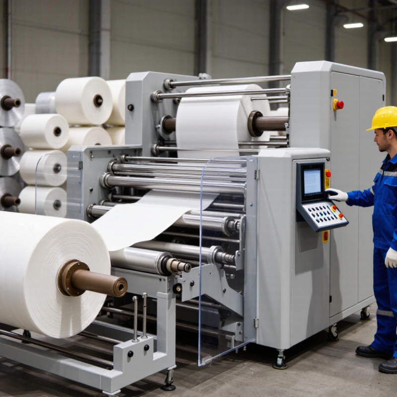
Table of Contents [Hide]
What Is an Insulation Wrapping Machine, and Where Is It Used?
2026 Best Insulation Wrapping Machine for Global Buyers?
What Is an Insulation Wrapping Machine, and Where Is It Used?
An insulation wrapping machine applies or secures insulation around products such as pipes, cables, and components. Depending on its design, it may feed material, control tension, overlap edges, and cut the wrap to length. Some machines handle protective outer layers rather than the insulation itself, so check the process carefully. Fit matters.
These machines are used in HVAC and refrigeration production, building-material workshops, and industrial pipe or cable manufacturing. A wrapped pipe section may need consistent coverage to reduce gaps and help protect the insulation during handling. On a production line, repeatable tension and wrap width can reduce variation between units. But results still depend on the material, operator setup, and product shape.
Tips: Confirm the machine supports your insulation’s thickness, width, and surface type. Ask for a trial using your actual product, and inspect seams, wrinkles, and cut edges. Not every line needs automation; for short runs, setup time may outweigh speed gains. That trade-off deserves a careful look.