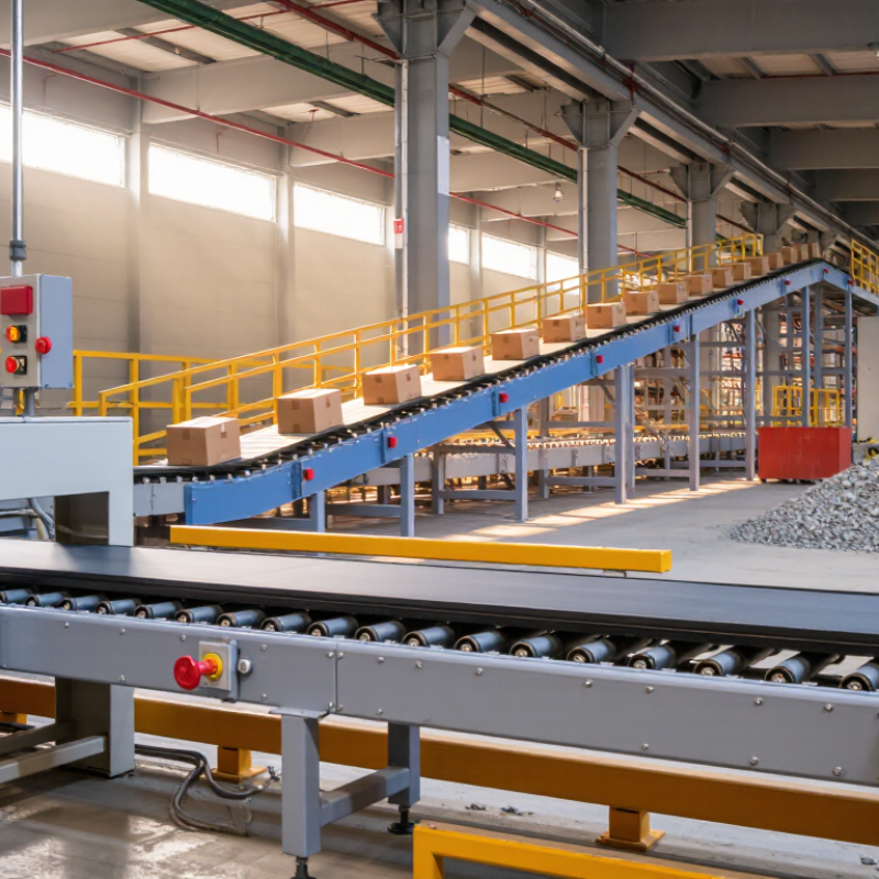
| Conveyor Belt | Carries bulk materials or unit loads along the conveying route. | Common belt materials include rubber, PVC, polyurethane, and fabric-reinforced elastomers. Belt strength and cover grade are selected according to load, abrasion, temperature, and material type. | The belt forms a continuous loop. Its carrying strand moves material forward while the return strand travels back to the tail end. | Check for cuts, edge damage, mistracking, excessive wear, splice condition, and abnormal stretching. |
| Head Pulley | Drives or redirects the belt at the discharge end. | Usually located at the head of the conveyor. A drive pulley may use a rubber lagging surface to improve traction and reduce belt slip. | When connected to the drive unit, the pulley transfers torque to the belt through friction and rotates the belt loop. | Inspect lagging wear, belt slippage, pulley alignment, bearing temperature, and material buildup. |
| Tail Pulley | Redirects the belt at the loading end and helps define the return path. | Positioned near the conveyor inlet. It may be fixed or arranged with take-up components depending on the conveyor design. | The belt wraps around the tail pulley and changes direction from the return strand to the carrying strand. | Check alignment, bearing condition, buildup, belt contact, and clearance around the loading zone. |
| Snub Pulley | Increases the belt wrap angle around a drive pulley. | Normally installed near the drive pulley. It is smaller than the main drive pulley in many conveyor layouts. | By increasing the contact area between belt and drive pulley, it can improve traction and reduce the likelihood of belt slip. | Inspect pulley alignment, bearing lubrication, surface condition, and belt tracking. |
| Carrying Idlers | Support the loaded carrying strand of the belt. | Frequently arranged in three-roll troughing sets for bulk materials. The trough angle is commonly selected from standard conveyor design options such as 20°, 35°, or 45°. | The rolls rotate as the moving belt passes over them, reducing sag and maintaining a controlled belt profile. | Look for seized rolls, unusual noise, damaged seals, uneven rotation, and belt contact with the frame. |
| Return Idlers | Support the empty belt on the return strand. | Often consists of single horizontal rolls, although disc or spiral designs may be used where material buildup is a concern. | Return rolls keep the belt from excessive sag and help maintain a stable path back to the tail pulley. | Check roll rotation, belt sag, material accumulation, and signs of belt rubbing. |
| Impact Idlers | Absorb impact at the loading point. | Typically fitted with rubber discs or resilient sleeves over the rolls. They are installed beneath the loading zone. | The resilient roll surface cushions falling material and distributes impact forces to reduce damage to the belt and support structure. | Inspect rubber discs, frame condition, spacing, belt indentation, and loading-point alignment. |
| Drive Unit | Provides the mechanical power required to move the belt and conveyed material. | Commonly includes an electric motor, gearbox or geared motor, couplings, and a drive pulley. Power is selected from calculated belt tension and conveyor resistance. | The motor produces rotational power, the transmission adjusts speed and torque, and the drive pulley applies the resulting force to the belt. | Monitor motor current, gearbox oil level, vibration, temperature, coupling condition, and unusual noise. |
| Take-Up Device | Maintains appropriate belt tension and compensates for belt stretch. | May be a screw take-up for shorter conveyors or a gravity take-up for longer conveyors and systems requiring more consistent tension. | It moves a pulley or tensioning assembly to remove slack, maintain traction, and help prevent belt slip. | Check available adjustment travel, tension stability, pulley alignment, counterweight movement, and cable or frame condition. |
| Conveyor Frame and Stringers | Supports pulleys, idlers, belt, drive equipment, and protective components. | Usually fabricated from structural steel, formed sections, or modular aluminum profiles for lighter-duty applications. | The structure keeps the conveyor components in the required relative positions and transfers operating loads to the foundations or support legs. | Inspect welds, bolts, corrosion, deflection, structural alignment, and damaged supports. |
| Loading Chute | Guides material onto the belt and controls the loading profile. | May include replaceable liners, skirt boards, sealing strips, and flow-control sections. Chute geometry depends on material properties and belt speed. | It directs material toward the belt center and helps limit excessive impact, dust generation, and spillage. | Check liner wear, blockages, skirt sealing, material buildup, and off-center loading. |
| Skirt Boards and Sealing System | Controls material at the loading point and reduces spillage and dust escape. | Usually consists of side plates with replaceable rubber or polymer sealing strips installed along the belt edges. | The seals remain close to the belt surface while allowing the belt to move through the loading zone. | Inspect sealing pressure, belt wear caused by excessive contact, gaps, and accumulated material. |
| Belt Cleaner | Removes residual material from the belt after discharge. | Primary cleaners commonly use polyurethane or carbide-tipped blades. Secondary cleaners are often installed farther along the return path. | A blade or brush contacts the belt surface and directs carryback into a collection area or back onto the material stream. | Check blade wear, contact pressure, mounting condition, belt damage, and carryback quantity. |
| Belt Tracking System | Keeps the belt centered on the conveyor structure. | May include training idlers, guide rollers, crowned pulleys, aligned frames, and electronic tracking devices. | Tracking components apply a corrective steering effect when the belt moves toward one side. | Look for edge wear, repeated side movement, misaligned idlers, off-center loading, and structural distortion. |
| Belt Scale | Measures the mass flow rate and total material conveyed. | A typical system uses a weigh frame, load cells, a belt-speed sensor, and an electronic integrator. | The load cells measure belt loading while the speed sensor measures belt velocity; the controller calculates mass flow and accumulated throughput. | Verify calibration, zero stability, belt tension, speed-sensor condition, and material centering. |
| Safety Pull Cord | Provides a manual emergency-stop function along accessible conveyor sections. | A tensioned wire rope is connected to switches installed at intervals along the conveyor. | Pulling the cord actuates the switch circuit and stops the conveyor drive when correctly integrated with the control system. | Test switch operation, rope tension, accessibility, reset function, and electrical response. |
| Belt Misalignment Switch | Detects excessive lateral belt movement. | Uses sensing rollers or levers positioned near the belt edges. | When the belt moves beyond a preset limit, the switch can generate an alarm or stop command to prevent edge damage and spillage. | Check switch alignment, activation distance, wiring, reset function, and response during controlled testing. |
| Emergency Stop and Control System | Controls starting, stopping, interlocking, and emergency shutdown functions. | May include motor starters or variable-frequency drives, programmable controllers, sensors, alarms, and local control stations. | The control system coordinates conveyor operation and prevents unsafe starts or continued operation when a critical fault is detected. | Test emergency stops, interlocks, alarm signals, restart protection, and control-panel condition. |
| Typical Belt Speed | Defines how quickly material travels along the conveyor. | Approximately 0.5–5 m/s for many industrial applications; the suitable value depends on material, belt width, dust, loading, and transfer requirements. | Higher speed can increase conveying capacity but may also increase dust, wear, spillage risk, and stopping distance. | Compare actual speed with the design value and check for unstable material flow or excessive carryback. |
| Common Belt Width Range | Determines the available carrying area and influences conveyor capacity. | Approximately 300–2,400 mm in many general industrial systems, with larger widths used for specialized high-capacity applications. | A wider belt can carry more material at a given loading profile and speed, subject to belt strength and equipment limitations. | Confirm width compatibility across pulleys, idlers, chutes, cleaners, and loading equipment. |
| Material Flow Capacity | Describes the amount of material moved per unit of time. | Usually expressed as t/h for bulk solids or units/min for packaged products. Capacity depends on belt width, speed, trough profile, loading cross-section, and bulk density. | The belt continuously transports material, allowing a steady flow between loading and discharge points. | Check actual throughput, loading consistency, belt scale readings, spillage, and motor loading. |