-
PRODUCTS & SERVICESOptimized cooling solutions for modern data centersProducts & ServicesOptimized cooling solutions for modern data centers
-
CAPABILITIESAdvancing liquid cooling technologiesCapabilitiesAdvancing liquid cooling technologies
-
TechnologiesLiquid Cooling InnovationTechnologiesLiquid Cooling Innovation
-
RESOURCESLatest News & InformationResourcesLatest News & Information
-
ABOUTOur history, leadership and ownershipAboutOur history, leadership and ownership
-
CONTACTFacility locations and global operational footprint






What Is an AC Wallbox Charger and How Does It Work?
As electric vehicle ownership expands, home charging is becoming essential rather than optional. The International Energy Agency’s Global EV Outlook 2025 reports that electric car sales exceeded 17 million in 2024. Electric vehicles represented more than one in five new cars sold worldwide. This growth increases demand for dependable residential charging equipment.
An Ac Wallbox Charger is a fixed charging unit installed beside a parking space. It connects the vehicle with the building’s AC electrical supply. When the charging cable is connected, the wallbox and vehicle exchange control signals. The system checks connection status, grounding, and available current before delivering power. The wallbox normally does not convert AC into battery DC. Instead, the vehicle’s onboard charger performs that conversion. Typical residential models provide between 3.6 and 22 kilowatts. Actual charging speed depends on wiring, vehicle capacity, and installation limits. A higher power rating does not always mean faster charging.
The U.S. Department of Energy’s Alternative Fuels Data Center describes Level 2 charging as commonly using 208–240-volt AC power. It generally charges much faster than a standard household outlet. In practical use, a 7.4-kilowatt wallbox may add meaningful range overnight, while a 22-kilowatt model can be limited by the vehicle itself. That distinction is easy to miss. IEC 61851-1 also defines important conductive charging control requirements. Safe installation still requires suitable protection, correct cable sizing, and qualified electrical work. The picture is not perfect. Weather, load management, and household demand can change results, so charger specifications should be read alongside real driving habits.
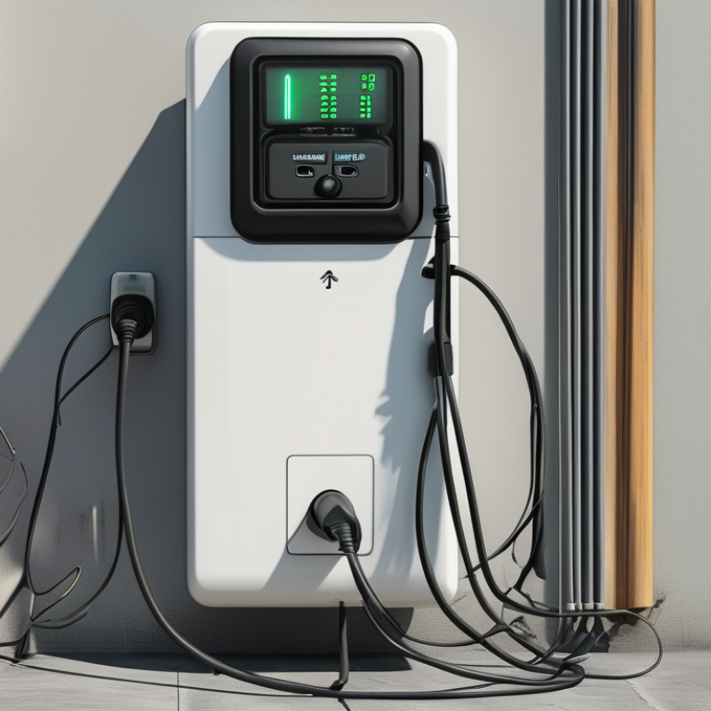
Table of Contents [Hide]
AC Wallbox Basics: 208–240 V Input and 3.7–22 kW Charging Output
An AC wallbox charger connects an electric vehicle to a building’s 208–240 V AC supply. Unlike a DC fast charger, it does not usually convert electricity inside the wallbox. The vehicle’s onboard charger performs that conversion, changing AC power into DC power for the battery.
Charging output commonly ranges from 3.7 to 22 kW. A 3.7 kW unit may use a modest current and suit overnight charging. A 7.4 kW wallbox often works with 240 V single-phase power and can add useful range during several hours. Higher outputs require stronger wiring, suitable circuit protection, and careful load calculations. A 22 kW rating may depend on three-phase power, so it is not automatically available from every 208–240 V installation.
The real charging speed depends on three limits: the wallbox, the vehicle’s onboard charger, and the electrical supply. The lowest limit controls the result. A car accepting only 11 kW will not charge at 22 kW, even when the wallbox supports it. A qualified electrician should verify conductor size, breaker capacity, grounding, and continuous-load requirements before installation. Small details matter.
In practice, smart load management can reduce output when a building uses ovens, heat pumps, or other heavy equipment. This prevents unnecessary upgrades, although it may extend charging time. The advertised power figure is useful, but it needs context.